 | –≠–ª–µ–∫—Ç—Ä–æ–Ω–Ω—ã–π –∫–æ–º–ø–æ–Ω–µ–Ω—Ç: EA2-5SNU | –°–∫–∞—á–∞—Ç—å:  PDF PDF  ZIP ZIP |
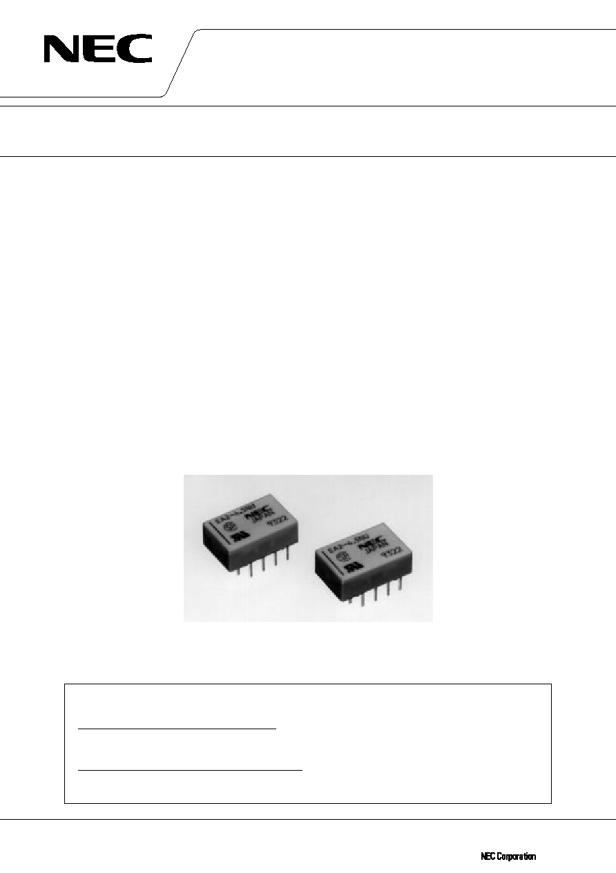
COMPACT AND LIGHTWEIGHT
DESCRIPTION
The EA2 series has reduced package size and power consumption to other NEC Conventional relays.
Furthermore, it complies with 1500 V surge-voltage requirement of FCC part 68 by the unique structure and the
efficient magnetic circuit
FEATURES
TM Low power consumption
TM Compact and light weight
TM 2 form c contact arrangement
TM Low magnetic arrangement
TM Breakdown voltage : 1000 Vac (surge voltage 1500 V), FCC Part 68 compliant
TM Tube packaging
TM UL recognized (E73266), CAS certified (LR46266)
APPLICATIONS
Electronic switching systems, PBX, key telephone systems, automatic test equipment and other electronic equip-
ment.
DATA S H E E T
EA2 SERIES
MINIATURE SIGNAL RELAY
ATTENTION
DO NOT EXCEED MAXIMUM RATINGS.
Do not use relays under exceeding conditions such as over ambient temperature, over voltage and over
current. Incorrect use could result in abnormal heating, damage to related parts or cause burning.
READ CAUTIONS IN THE SELECTION GUIDE.
Read the cautions described in NEC's "Miniature Relays" (ER0046EJ
) when you choose relays for
your application.
Document No. ER0001EJ6V0DS00 (6th edition)
Date Published June 1999 M
Printed in Japan
©
1989 (1996)
2
EA2 SERIES
DATA SHEET ER0001EJ6V0DS00
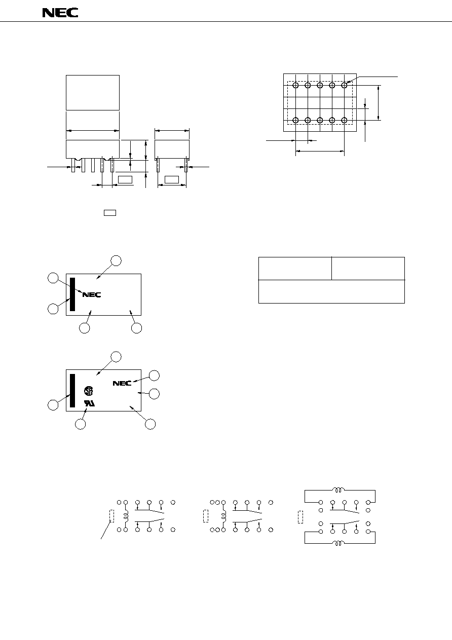
OUTLINE DRAWING AND DIMENSIONS
PAD LAYOUT (bottom view)
Unit : mm (inch)
PIN CONFIGURATIONS
MARKINGS
14.2 max.
(0.56)
9.2 max.
(0.36)
0.5
(0.02)
0.25
(0.01)
5.4 max.
(0.21)
0.33 (0.013)
3.5
2.54
(0.10)
7.62
(0.30)
Note. tolerance 0.2 ( 0.008) unless otherwise specified
Dimensions in show basic size.
NJ type : Cover height-6.3 mm (0.248), Leads-2.8 mm (0.11)
+
≠
+
≠
10- 0.8(0.03)
10.16
(0.40)
2.54
(0.10)
7.62
(0.30)
2.54
(0.10)
Note. Tolerance 0.1 ( 0.004) unless othewise specified
+
≠
+
≠
EA2-5NU
9106
JAPAN
JAPAN
1
2
3
4
6
5
EA2-5
9106
1
4
3
5
2
q Part number
w Manufacturer
e Country of origin
r Date code
t Index mark of relay direction
(pin No. 1, 10.)
y UL, CSA Marking
Standard type
UL recognized,
CSA certified type
+
≠
+
+ ≠
≠
+
+
≠
≠
1
2
3
4
5
10
9
8
7
6
1
2
3
4
5
1
2
3
S
R
4
5
10
9
8
R S
7
6
10
9
8
7
6
Index mark of
relay direction
Non-latch type
(not energized position)
Single coil latch type
(reset position)
Double coil latch type
(reset position)
S : Coil polarity of set (operate)
R : Coil polarity of reset (release)
SAFETY STANDARD AND RATING
UL Recognized
(UL508)
File No E73266
CSA Certificated
(CSA C22.2 No 14)
File No LR46266
30 Vdc, 1 A
(Resistive)
110 Vdc, 0.3 A (Resistive)
125 Vdc, 0.5 A (Resistive)
Spacing : UL114, UL478
3
DATA SHEET ER0001EJ6V0DS00
EA2 SERIES
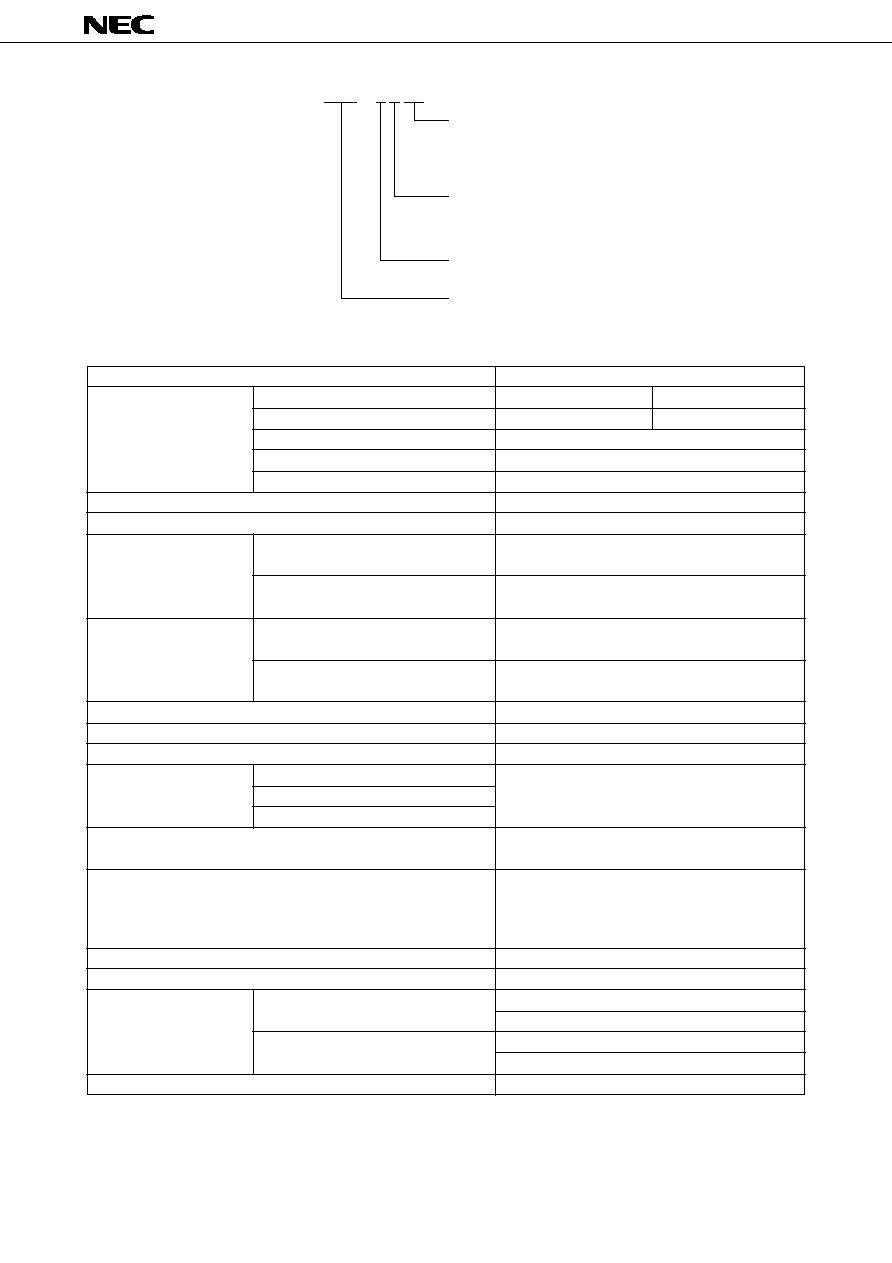
PART NUMBER SYSTEM
E A 2 ≠ 3 S NU
Nil : Standard type
NU : UL recognized, CSA certified type
NJ : Trimmed leads type
NP : Silver-palladium alloy contact (with gold alloy overlay)
Latch type
Nil : Non-latch type (standard type)
S : Single coil latch type
T : Double coil latch type
Nominal coil voltage
3, 4.5, 5, 6, 9, 12, 24 Volts
EA2 series
UL recognized, CAS certified type
2 form c
30 W (resistive)
62.5 VA (resistive)
220 Vdc
250 Vac
1 A
2 A
10 mVdc, 10
µ
A
1
50 m
typ. (Initial)
Silver alloy with gold alloy overlay
140 mW (3 to 12 V)
200 mW (24 V)
100 mW (3 to 12 V)
150 mW (24 V)
79 mW (3 to 12 V)
113 mW (24 V)
56 mW (3 to 12 V)
85 mW (24 V)
Approximately 2 ms without diode
Approximately 1 ms without diode
1000 M
at 500 Vdc
1000 Vac (for one minute)
1500 V surge (10
◊
160
µ
s
2
)
735 m / s
2
(75 G) (misoperating)
980 m / s
2
(100 G) (destructive failure)
10 to 55 Hz at double amplitude of 3 mm (20 G)
(misoperating)
10 to 55 Hz, at double amplitude of 5 mm (30 G)
(destructive failure)
≠40
∞
C to 85
∞
C
18 degrees at nominal coil voltage
1
◊
10
8
operations (Non-latch type)
3
1
◊
10
7
operations (latch type)
50 Vdc 0.1 A (resistive), 1
◊
10
6
operations at 85∞C, 2 Hz
10 Vdc 10 mA (resistive), 1
◊
10
6
operations at 85∞C, 2 Hz
Approximately 1.5 grams
Contact Form
Maximum switching power
Maximum switching voltage
Maximum switching current
Maximum carrying current
Minimum contact ratings
Initial contact resistance
Contact material
Non-latch type and double coil latch type
Single coil Latch type
Non-latch type and double coil latch type
Single coil latch type
Operate time (excluding bounce)
Release time (excluding bounce)
Insulation resistance
Between open contacts
Breakdown voltage
Between adjacent contacts
Between coil and contact
Shock resistance
Vibration resistance
Ambient temperature
Coil temperature rise
Noload
Load
Weight
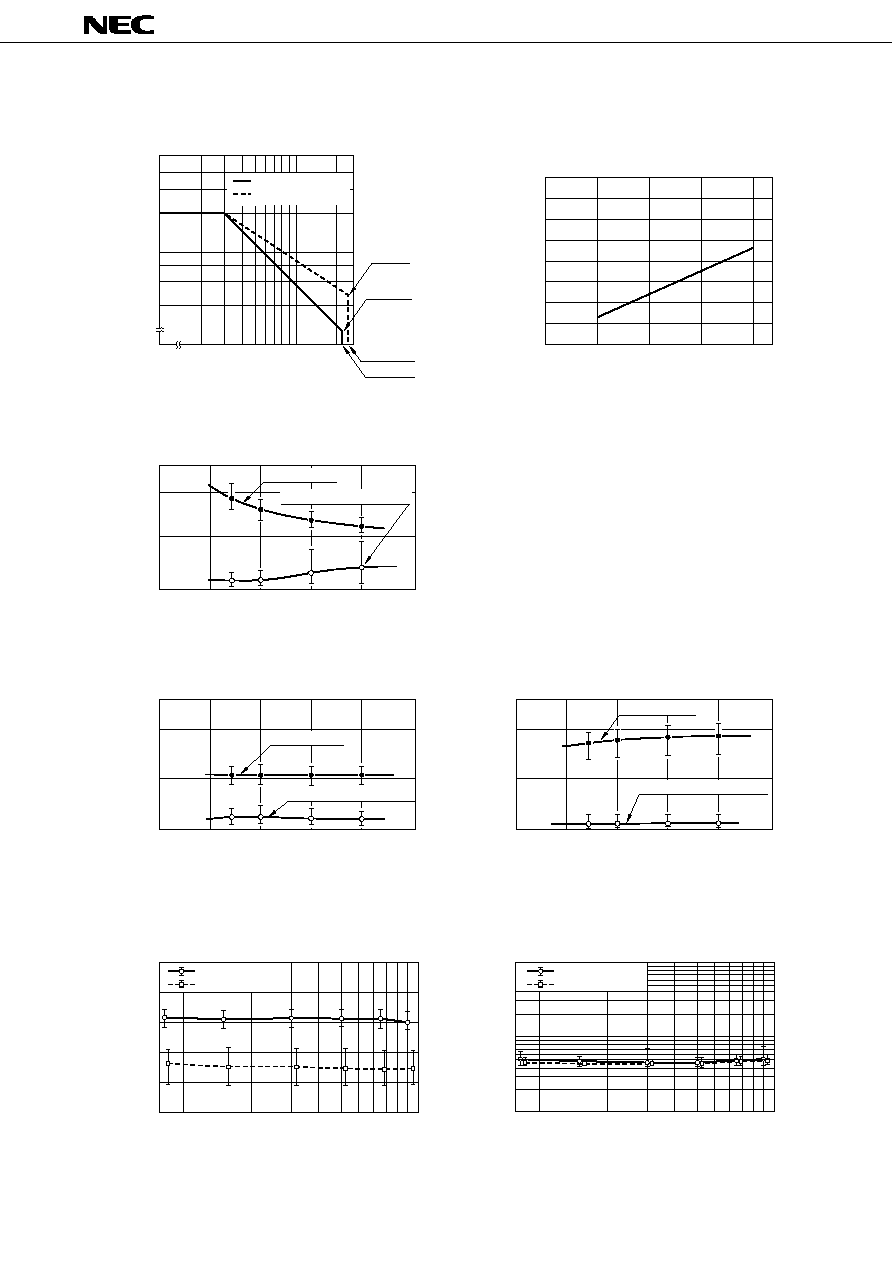
PERFORMANCE CHARACTERISTICS
1
This value is a reference value in the resistance load.
Minimum capacity changes depending on seitching frequency and environment temperature and the load.
2
Rise time : 10
µ
s, fall time : 160
µ
s
3
This shows a number of operation where it can be running by which a fatal defect is not caused, and a number of
operation by which a steady characteristic is maintained is 1
◊
10
7
times.
Minimum operating Power
Nominal operating Power
Running specifications
Contact rating
4
EA2 SERIES
DATA SHEET ER0001EJ6V0DS00
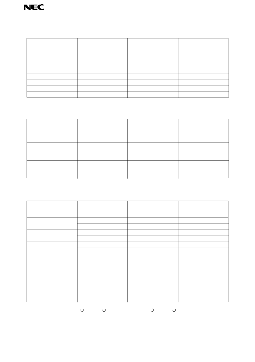
PRODUCT LINEUP
Non-latch Type
Nominal Coil
Voltage
(Vdc)
3
4.5
5
6
9
12
24
Coil
Resistance
(
)
±
10 %
64.3
145
178
257
579
1028
2880
Must Operate
Voltage
(Vdc)
2.25
3.38
3.75
4.5
6.75
9
18
Must Release
Voltage
(Vdc)
0.3
0.45
0.5
0.6
0.9
1.2
2.4
Single-Coil Latch Type
at 20∞C
at 20∞C
at 20∞C
Nominal Coil
Voltage
(Vdc)
3
4.5
5
6
9
12
24
Coil
Resistance
(
)
±
10 %
S
64.3
R
64.3
S
145
R
145
S
178
R
178
S
257
R
257
S
579
R
579
S
1028
R
1028
S
2880
R
2880
Must Operate
Voltage
(Vdc)
2.25
≠
3.38
≠
3.75
≠
4.5
≠
6.75
≠
9
≠
18
≠
Must Release
Voltage
(Vdc)
≠
2.25
≠
3.38
≠
3.75
≠
4.5
≠
6.75
≠
9
≠
18
Double-Coil Latch Type
(Can not be driven by revese polarity for reverse operation.)
Note
Test by pulse voltage
S : Set coil (pin No.1... , pin No.5... ) R : Reset coil (pin No.10... , pin No.6... )
The latch type relays should be initalized at appointed position before using, and should be enegized to specific
polanity by a bone polabity to avoid wrong operation.
Any special coil requirement, please contact NEC for availability.
Nominal Coil
Voltage
(Vdc)
3
4.5
5
6
9
12
24
Coil
Resistance
(
)
±
10 %
90
202.5
250
360
810
1440
3840
Must Operate
Voltage
(Vdc)
2.25
3.38
3.75
4.5
6.75
9
18
Must Release
Voltage
(Vdc)
2.25
3.38
3.75
4.5
6.75
9
18
+
≠
+
≠
5
DATA SHEET ER0001EJ6V0DS00
EA2 SERIES
2.0
80
60
40
20
0
1.0
0.5
0.4
0.3
0.2
30
100
200
220 Vdc
250 Vdc
0.25A
0.136A
DC Load (resistive)
AC Load (resistive)
Switching Voltage (V)
Applied Power (mW)
Applied Power (mW)
Sample : EA2-5 n = 10
Load : None
Temperature : 85∞C
Drive : 5 Vdc, 10 Hz 50% duty
Applied Power (mW)
100
200
300
400
Applied Power (mW)
SWITCHING CAPACITY
OPERATE TIME
RELEASE TIME WITHOUT DIODE
RUNNING SPECIFICATIONS (Noload)
RELEASE TIME WITH DIODE
COIL TEMPERATURE RISE
Switching Current (A)
Release Time or
Bounce Time at Release (ms)
Release Time or
Bounce Time at Release (ms)
Release Time or
Bounce Time at Release (ms)
Operate Voltage or
Release Voltage (V)
Contact Resistance (m
)
Coil Temperature Rise (∞C)
2
1
0
100
200
300
500
400
2
1
0
100
200
300
500
400
Bounce Time at Operate
Bounce Time at Release
Bounce Time at Release
Operate Time
Release Time
2
1
0
100
200
300
500
400
Operate Voltage
Release Voltage
Make contact
Break contact
0
1
1
2
3
4
5
2
3
Number of Operations (
◊
10
6
operations)
Number of Operations (
◊
10
6
operations)
5
10
0
1
1000
500
300
200
100
50
30
20
10
2
3
5
10
Release Time
TYPICAL PERFORMANCE DATA